
Significant Factors Of Data cabling - Ideas To Consider
Ethernet Cable: Types, Performance & Pinout - Cat 5, 5e, 6, 6a, 7, 8
There are many Ethernet cables that can be bought. Often these cables are supplied free with equipment that uses Ethernet connectivity in some way or another.
There are several different varieties of Ethernet cable that can be obtained: speed variations, crossover cables, Cat 5, Cat 5e, Cat6, Cat 6a, Cat 7etc..
Normally Ethernet cables will be bought and there is no major need to understand what is inside or on the connectors, although it can be both interesting and helpful on some occasions. Even so, an understanding of the different types of Ethernet cable and the maximum lengths that should be used is helpful.
The commonly used network cables: Cat 5, Cat 5e, Cat 6, Cat 6a, Cat7 all have different levels of performance, and therefore to is necessary to buy or select the right cable for the right application.
These network cables are used for connecting a variety of network elements from Ethernet switches and Ethernet routers to computers, servers and other network items - if there is an Ethernet interface, they can be connected using Ethernet cables.
Typical Ethernet cable supplied with many computers, Ethernet routers, etc
Typical Ethernet cable supplied with many computers, routers, etc
Ethernet cable basics
The Ethernet cables for connectivity in most office and home environments rely on twisted wire pairs within an overall cable - Cat 5, Cat 6 and Cat 7 all used this format. Twisting the wires together enables the currents to balance, i.e in one wire the current is moving in one direction, and int he other wire of the pair the current is going in the other, enabling the overall fields around the twisted pair to cancel.
In this way, data can be transmitted over considerable lengths without the need for undue precautions.
As several twisted pairs are contained within a particular network cable, the number of twisted per unit length is arranged to be different for each pair - the rate being based on prime numbers so that no two twists ever align. This reduces crosstalk within the cable.
The Ethernet cables are available in a variety of lengths as patch cables, or the cable itself is available for incorporating into systems, buildings, etc. The terminations can then be made to the required connector using a crimp tool. These network cables are available in a variety of lengths - long Ethernet cables are available, some of the longest being up to 75 metres.
Earlier network cables were unshielded, but later ones were shielded to improve the performance. For example an unshielded twisted pair (UTP) cable may be satisfactory for a short run between a computer and router, but a foil shielded cable, FTP, is best longer runs or where the cable passes through areas of high electrical noise.
Ethernet cable and connector used for connecting items including Ethernet switches, Ethernet routers, computers, network servers, etc.
Flat Ethernet cable and connector
There are different methods that can be used for shielding Ethernet cables. The most common is to place a shield around each twisted pair. This not only provides shielding for the cable externally, but also reduces crosstalk between the internal twisted pairs as well. Manufacturers can further enhance the performance by placing shielding around all the wires in the cable just under the cable sheath. There are different codes used to indicate the differs types of shielding:
U/UTP - Unshielded cable, unshielded twisted pairs
F/UTP - Foil shielded cable, unshielded twisted pairs
U/FTP - Unshielded cable, foil shielded twisted pairs
S/FTP - braided shielded cable, foil shielded twisted pairs
Where: TP = twisted pair, U = unshielded, F = foil shielded, S = braided shielding.
A further difference within the Ethernet cables whether Cat 5, Cat 5e, Cat 6, Cat 6e, or Cat 7 can be whether solid or stranded wires are used within the cable. As the description implies, a solid cable uses a single piece of copper for the electrical conductor within each wire of the cable whilst stranded wire uses a series of copper strands twisted together. Although when buying a patch cable, it may not be necessary to know this, when installing a long cable run it may be important as each type is slightly more suitable for different applications.
Stranded cable: This type of wire is more flexible and it is more applicable for Ethernet cables where the cable may be moved - often it is idea for patch leads at desks or general connections to PCs, etc where some movement may be needed and expected.
Solid cable: Solid cable is not as flexible as the stranded type, but it is also more durable. This makes it best for use in permanent installations like cable installations under floors, embedded in walls and the like.
Categories for Ethernet cables
A variety of different cables are available for Ethernet and other telecommunications and networking applications. These network cables that are described by their different categories, e.g. Cat 5 cables, Cat-6 cables, etc, which are often recognised by the TIA (telecommunications Industries Association) and they are summarised below:
Cat-1: This is not recognised by the TIA/EIA. It is the form of wiring that is used for standard telephone (POTS) wiring, or for ISDN.
Cat-2: This is not recognised by theTIA/EIA. It was the form of wiring that was used for 4Mbit/s token ring networks.
Cat-3: This cable is defined in TIA/EIA-568-B. It is used for data networks employing frequencies up to 16 MHz. It was popular for use with 10 Mbps Ethernet networks (100Base-T), but has now been superseded by Cat-5 cable.
Cat-4: This cable is not recognised by the TIA/EIA. However data cabling installation services can be used for networks carrying frequencies up to 20 MHz. It was often used on 16Mbps token ring networks.
Cat-5: This is not recognised by the TIA/EIA. This is the network cable that is widely used for 100Base-T and 1000Base-T networks as it provides performance to allow data at 100 Mbps and slightly more (125 MHz for 1000Base-T) Ethernet. The Cat 5 cable superseded the Cat 3 version and for a number of years it became the standard for Ethernet cabling. Cat 5 cable is now obsolete and therefore it is not recommended for new installations.
Cat 5 cable uses twisted pairs to prevent internal crosstalk, XT and also crosstalk to external wires, AXT.
Although not standardised, the Cat 5 cable normally uses 1.5 - 2 twists per centimetre.
This article below involving Ethernet cabling installation is indeed insightful. Give it a go and make your own conclusions.
Structured wiring - low voltage description
Normally, low voltage wiring is an assembly of cable television and parts for whatever that is different from standard electrical wiring for mid to greater voltage product requirements. These products consist of: lights, switches, power outlets, and direct connections for powering equipment such as heating and cooling systems. The low voltage we're speaking about is for communication and other equipment that uses 50 volts of electrical power and less. It also provides a pathway for different digital technology systems to link, communicate and share data. These systems consist of voice/phone and data, security and intercom and more!. This is achieved utilizing a variety of low voltage network cabling choices.
Structured wiring installation and requirements
Low voltage wiring. It's all over. The rapid and continuous expansion of innovation from simple wiring for telegraph and telephones to intricate structured cabling networks for data, voice, audio/visual, wi-fi, and lots of other systems has actually produced an electrical industry specialty. Commercial building and construction companies recognize there's more to the electrical requirements of new structure construction than lights and power outlets and that a lot of electrical professionals do not always focus their work force on low voltage abilities. They hire a certified specialty low voltage company to style, construct and set up low voltage and structured wiring infrastructures that will supply efficient and optimized communication and digital technology network performance. The terms Low Voltage Wiring and Structured Cabling are typically interchanged but what's crucial is knowing that every installation is unique. Numerous products are factored into a design of a structured cabling system. These include: the structure of the building and/or center, the floor plan of interior space, needs and work circulation of the present work force and plans for future growth. Optimal function needs cautious preparation and an efficient network.
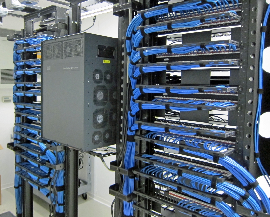
A low voltage structured cabling system is one of the most important structures of your network for voice and data in a building or school. It is the organized collection of copper or fiber wiring and other components in walls, ceilings, conduit, and elsewhere that connect all your IT hardware of computers, telephones, security video cameras, photo copiers, entry access points, and more to your networks for phone and data. This facilities collection is unique for each building installation and includes patch panels, trunks, and a range of other components besides low voltage data cabling. It is what makes telecommunication options possible. This system can be likened to the central nerve system in the human body where the spinal cord, nerve paths and end points are the avenues for signals in between the body and brain. When designed well, low voltage network cabling supplies versatility, optimizes uptime, is quickly scalable for future increased usage requirements and is a great roi (ROI). It likewise can decrease costs by restricting down time and associated loss of performance. A correctly developed and installed system likewise looks cleaner and makes it much easier to implement modifications to the network. Who hasn't experienced messy cabling that is challenging to determine what is going where?
Ethernet Wiring Installation
Ethernet cable television setups are typically used to link gadgets like PC's and routers together within a local network. Different classifications of copper based Ethernet cable televisions are used depending upon the required speed of data transmission and the distance between the connected devices. Cat5 cable televisions are most common and support data transmission speeds at 10 to 100 Mbps in between connections of around 300 feet, after which there is a loss of communication signal strength. Feline 5e (boosted) supports data transmission up to 1000 Mbps. Cat 6 structured cabling supports even faster data transmission to 10Gbps and can add to 700 feet before signal loss. Fiber optic installations are best for fastest speeds and even higher ranges. Fiber cable is made from glass strands as opposed to Ethernet's copper. Glass carries digital details with light instead of electrical currents brought by copper.
Voice and Data Cable Install Service
Voice and data cable television installations for phone systems and web connection utilize the very same classifications of copper based Ethernet and glass based fiber optic cabling, depending upon the requirements of the end user. Phone and data cabling is gone through the walls and ceilings of a work location to every cubicle and workplace to link gadgets back to telephone closets/telecommunication enclosures and server rooms.

Major Factors For Data cabling Explained
The Six Subsystems of a Structured Cabling System
This information is based on two standards: ANSI/TIA-568-C.0 (Generic Telecommunications Cabling for Customer Premises), which is used for generic infrastructures, and ANSI/TIA-568-C.1 (Commercial Building Telecommunications Cabling Standard), which is more commonly used with typical commercial building infrastructures.
Six Subsystems that make up a Structured Cabling System
1. Entrance Facilities (EF)
Entrance facilities contain the cables, network demarcation point(s), connecting hardware, protection devices and other equipment that connect to the access provider (AP) or private network cabling. It includes connections between outside plant and inside building cabling.
2. Equipment Room (ER)
The environmentally controlled centralized space for telecommunications equipment is usually more complex than a telecommunications room (TR) or telecommunications enclosure (TE). It usually houses the main cross-connect (MC) [Distributor C] and may also contain the intermediate cross-connects (ICs) [Distributor B], horizontal cross-connects (HCs) [Distributor A], or both.
3. Backbone Cabling
The backbone cabling provides interconnection between telecommunications rooms, equipment rooms, access provider (AP) spaces and entrance facilities. There are two subsystems defined for backbone cabling:
Cabling Subsystem 2 – Backbone cabling between the horizontal cross-connect (HC) [Distributor A (DA)] and the intermediate cross-connect (IC) [Distributor B (DB)]
Cabling Subsystem 3 – Backbone cabling between an intermediate cross-connect
(IC) [Distributor B (DB)] and the main cross-connect (MC) [Distributor C (DC)]
Recognized cabling:
100-ohm twisted-pair cabling: Category 3, Category 5e, Category 6 or Category 6A
Multimode optical fiber cabling: 850 nm laser-optimized 50/125 μm is recommended; 62.5/125 μm and 50/125 μm is allowed
Single-mode optical fiber cabling
4. Telecommunications Room (TR) and Telecommunications Enclosure (TE)
A TR or TE houses the terminations of horizontal and backbone cables to connecting hardware including any jumpers or patch cords. It may also contain the IC or MC for different portions of the backbone cabling system. The TR or TE also provides a controlled environment to house telecommunications equipment, connecting hardware and splice closures serving a portion of the building.
The use of a telecommunications enclosure (TE) is for a specific implementation and not a general case. It is intended to serve a smaller floor area than a TR and may be used in addition to the minimum "one TR per floor" rule.
5. Horizontal Cabling – (Cabling Subsystem 1)
The horizontal cabling system extends from the work area’s telecommunications information outlet to the telecommunications room (TR) or telecommunications enclosure (TE). It includes horizontal cable, mechanical terminations, jumpers and patch cords located in the TR or TE and may incorporate multiuser telecommunications outlet assemblies (MUTOAs) and consolidation points (CPs). The maximum horizontal cable length shall be 90 m (295 ft.), independent of media type. If a MUTOA is deployed, the maximum horizontal balanced twisted-pair copper cable length shall be reduced.
Recognized cabling:
4-pair 100-ohm unshielded or shielded twisted-pair cabling:
Category 5e, Category 6 or Category 6A
Multimode optical fiber cabling, 2-fiber (or higher fiber count)
Single-mode optical fiber cabling, 2-fiber (or higher fiber count)
Horizontal Cabling Maximum Distances and Information Outlets
6. Work Area
Work area (WA) components extend from the telecommunications outlet/connector end of the horizontal cabling system to the WA equipment.
A minimum of two telecommunications outlets (permanent links) should be provided for each work area. Multiuser telecommunications outlet assemblies (MUTOAs), if used, are part of the WA.
Just how do you feel when it comes to Cat6 installation?
Server room installation Sacramento : 0; top: 0; left: 0; width: 80%; height: 85%; position: relative;" allowfullscreen allow="encrypted-media; accelerometer; gyroscope; picture-in-picture">
Structured cabling - low voltage description
Usually, low voltage wiring is an assembly of cable television and parts for everything that is different from basic electrical wiring for mid to greater voltage item needs. These items include: lights, switches, power outlets, and direct connections for powering devices such as heating and cooling systems. The low voltage we're speaking about is for communication and other equipment that uses 50 volts of electricity and less. It likewise offers a pathway for various digital innovation systems to connect, communicate and share data. These systems consist of voice/phone and data, security and intercom and more!. This is accomplished utilizing a variety of low voltage network cabling options.
Structured wiring setup and requirements
Low voltage wiring. It's all over. The quick and constant growth of technology from basic wiring for telegraph and telephones to complicated structured cabling networks for data, voice, audio/visual, wi-fi, and numerous other systems has developed an electrical industry specialized. Commercial building and construction companies recognize there's more to the electrical requirements of new building construction than lights and power outlets and that the majority of electrical professionals do not always focus their labor force on low voltage abilities. They hire a certified specialty low voltage company to design, build and install low voltage and structured wiring facilities that will provide effective and enhanced communication and digital innovation network performance. The terms Low Voltage Wiring and Structured Cabling are often interchanged however what's essential is knowing that every installation is unique. Numerous items are factored into a design of a structured cabling system. These consist of: the structure of the structure and/or facility, the layout of interior space, requires and work flow of the present work force and plans for future development. Optimal function needs mindful planning and an efficient network.
A low voltage structured cabling system is one of the most essential foundations of your network for voice and data in a building or school. It is the organized collection of copper or fiber wiring and other elements in walls, ceilings, conduit, and somewhere else that connect all your IT hardware of computers, telephones, security cams, copiers, entry access points, and more to your networks for phone and data. This facilities collection is distinct for each structure installation and consists of patch panels, trunks, and a range of other components besides low voltage data cabling. It is what makes telecommunication services possible. This system can be compared to the main nervous system in the body where the spine, nerve paths and end points are the avenues for signals in between the body and brain. When developed well, low voltage network cabling supplies flexibility, enhances uptime, is easily scalable for future increased use requirements and is an excellent roi (ROI). It also can minimize expenses by restricting down time and involved loss of productivity. An appropriately developed and installed system also looks cleaner and makes it much easier to implement changes to the network. Who hasn't experienced messy cabling that is difficult to figure out what is going where?
Cat6 Wiring Install
Ethernet cable television setups are commonly utilized to connect devices like PC's and routers together within a regional network. Various categories of copper based Ethernet cables are utilized depending on the needed speed of data transmission and the range between the linked equipment. Cat5 cable televisions are most typical and support data transmission speeds at 10 to 100 Mbps between connections of around 300 feet, after which there is a loss of communication signal strength. Feline 5e (boosted) supports data transmission as much as 1000 Mbps. Cat 6 structured cabling supports even faster data transmission to 10Gbps and can add to 700 feet prior to signal loss. Fiber optic setups are best for fastest speeds and even higher distances. Fiber cable is made of glass strands rather than Ethernet's copper. Glass carries digital information with light instead of electrical currents brought by copper.
Voice and Data Cable Companies
Voice and data cable television setups for phone systems and web connection utilize the exact same classifications of copper based Ethernet and glass based fiber optic cabling, depending upon the requirements of completion user. Phone and data cabling is run through the walls and ceilings of a work place to every cubicle and workplace to link devices back to telephone closets/telecommunication enclosures and server spaces.

No-Hassle Programs Of Cat6 installation
In this article in the next paragraphs you can locate a bunch of dependable guidance regarding Cat6 installation.
The Six Subsystems of a Structured Cabling System
This information is based on two standards: ANSI/TIA-568-C.0 (Generic Telecommunications Cabling for Customer Premises), which is used for generic infrastructures, and ANSI/TIA-568-C.1 (Commercial Building Telecommunications Cabling Standard), which is more commonly used with typical commercial building infrastructures.
Six Subsystems that make up a Structured Cabling System
1. Entrance Facilities (EF)
Entrance facilities contain the cables, network demarcation point(s), connecting hardware, protection devices and other equipment that connect to the access provider (AP) or private network cabling. It includes connections between outside plant and inside building cabling.
2. Equipment Room (ER)
The environmentally controlled centralized space for telecommunications equipment is usually more complex than a telecommunications room (TR) or telecommunications enclosure (TE). It usually houses the main cross-connect (MC) [Distributor C] and may also contain the intermediate cross-connects (ICs) [Distributor B], horizontal cross-connects (HCs) [Distributor A], or both.
3. Backbone Cabling
The backbone cabling provides interconnection between telecommunications rooms, equipment rooms, access provider (AP) spaces and entrance facilities. There are network cabling contractors near me defined for backbone cabling:
Cabling Subsystem 2 – Backbone cabling between the horizontal cross-connect (HC) [Distributor A (DA)] and the intermediate cross-connect (IC) [Distributor B (DB)]
Cabling Subsystem 3 – Backbone cabling between an intermediate cross-connect
(IC) [Distributor B (DB)] and the main cross-connect (MC) [Distributor C (DC)]
Recognized cabling:
100-ohm twisted-pair cabling: Category 3, Category 5e, Category 6 or Category 6A
Multimode optical fiber cabling: 850 nm laser-optimized 50/125 μm is recommended; 62.5/125 μm and 50/125 μm is allowed
Single-mode optical fiber cabling
4. Telecommunications Room (TR) and Telecommunications Enclosure (TE)
A TR or TE houses the terminations of horizontal and backbone cables to connecting hardware including any jumpers or patch cords. It may also contain the IC or MC for different portions of the backbone cabling system. The TR or TE also provides a controlled environment to house telecommunications equipment, connecting hardware and splice closures serving a portion of the building.
The use of a telecommunications enclosure (TE) is for a specific implementation and not a general case. It is intended to serve a smaller floor area than a TR and may be used in addition to the minimum "one TR per floor" rule.
5. Horizontal Cabling – (Cabling Subsystem 1)
The horizontal cabling system extends from the work area’s telecommunications information outlet to the telecommunications room (TR) or telecommunications enclosure (TE). It includes horizontal cable, mechanical terminations, jumpers and patch cords located in the TR or TE and may incorporate multiuser telecommunications outlet assemblies (MUTOAs) and consolidation points (CPs). The maximum horizontal cable length shall be 90 m (295 ft.), independent of media type. If a MUTOA is deployed, the maximum horizontal balanced twisted-pair copper cable length shall be reduced.
Recognized cabling:
4-pair 100-ohm unshielded or shielded twisted-pair cabling:
Category 5e, Category 6 or Category 6A
Multimode optical fiber cabling, 2-fiber (or higher fiber count)
Single-mode optical fiber cabling, 2-fiber (or higher fiber count)
Horizontal Cabling Maximum Distances and Information Outlets
6. Work Area
Work area (WA) components extend from the telecommunications outlet/connector end of the horizontal cabling system to the WA equipment.
A minimum of two telecommunications outlets (permanent links) should be provided for each work area. Multiuser telecommunications outlet assemblies (MUTOAs), if used, are part of the WA.
Structured cabling - low voltage description
Generally, low voltage wiring is an assembly of cable television and parts for everything that is different from basic electrical wiring for mid to greater voltage item needs. These products include: light fixtures, switches, power outlets, and direct connections for powering devices such as heating and cooling systems. The low voltage we're discussing is for communication and other devices that utilizes 50 volts of electrical power and less. It also offers a pathway for various digital innovation systems to connect, communicate and share data. These systems include voice/phone and data, security and intercom and more!. This is accomplished using a variety of low voltage network cabling options.
Structured wiring setup and standards
Low voltage wiring. It's everywhere. The rapid and continuous growth of innovation from basic wiring for telegraph and telephones to complex structured cabling networks for data, voice, audio/visual, wi-fi, and many other systems has produced an electrical market specialized. Commercial building business recognize there's more to the electrical requirements of new building construction than lights and power outlets which the majority of electrical contractors do not always focus their labor force on low voltage abilities. They work with a qualified specialty low voltage business to design, build and set up low voltage and structured wiring facilities that will supply effective and optimized communication and digital innovation network efficiency. The terms Low Voltage Wiring and Structured Cabling are frequently interchanged but what's essential is knowing that every installation is distinct. Numerous items are factored into a style of a structured cabling system. These include: the structure of the building and/or facility, the floor plan of interior area, requires and work flow of the present labor force and plans for future growth. Maximum function needs cautious planning and an effective network.
A low voltage structured cabling system is among the most important foundations of your network for voice and data in a structure or school. It is the organized collection of copper or fiber wiring and other parts in walls, ceilings, avenue, and in other places that link all your IT hardware of computer systems, telephones, security cameras, copiers, entry access points, and more to your networks for phone and data. This infrastructure collection is special for each structure installation and consists of spot panels, trunks, and a variety of other elements besides low voltage data cabling. It is what makes telecommunication services possible. This system can be likened to the central nervous system in the body where the spine, nerve paths and end points are the avenues for signals in between the body and brain. When created well, low voltage network cabling provides flexibility, optimizes uptime, is easily scalable for future increased use needs and is a good roi (ROI). It likewise can decrease costs by restricting down time and involved loss of productivity. An appropriately designed and installed system likewise looks cleaner and makes it simpler to execute changes to the network. Who hasn't witnessed unpleasant cabling that is challenging to determine what is going where?
data Cabling Install
Ethernet cable television installations are typically used to link devices like PC's and routers together within a regional network. Various categories of copper based Ethernet cable televisions are utilized depending upon the required speed of data transmission and the distance between the connected equipment. Cat5 cables are most typical and support data transmission speeds at 10 to 100 Mbps in between connections of around 300 feet, after which there is a loss of communication signal strength. Feline 5e (boosted) supports data transmission approximately 1000 Mbps. Feline 6 structured cabling supports even quicker data transmission to 10Gbps and can run up to 700 feet prior to signal loss. Fiber optic setups are best for fastest speeds and even greater ranges. Fiber cable is made of glass strands rather than Ethernet's copper. Glass carries digital details with light instead of electrical currents brought by copper.
Voice and Data Cable Installation Service
Voice and data cable installations for phone systems and web connection utilize the same classifications of copper based Ethernet and glass based fiber optic cabling, depending upon the requirements of completion user. Phone and data cabling is run through the walls and ceilings of a work place to every cubicle and office to link gadgets back to telephone closets/telecommunication enclosures and server spaces.
